
Wiring & pinouts
Every pin, wire colour and lead label on the three FusionDrive harnesses, how the plugs are numbered, and typical wiring diagrams for the loads and sensors people fit most often.
Work with the battery disconnected. Fuse every load. Never apply 12 V to a sensor input, never connect always-on power to the IGN lead, and validate the actual load, cable, fuse and thermal capability. Nominal lead markings are not continuous-current qualification. Values not listed here are in the specifications.
The connector face
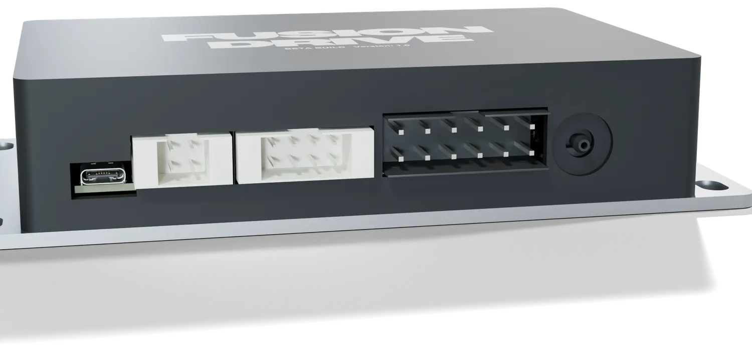
| Port | Ways | Harness | Carries |
|---|---|---|---|
| Service port | — | none | Workshop and support use only. Not needed for installation or updates. |
| OBD port | 4 | Harness A (1.5 m) | Vehicle 12 V, ground, vehicle CAN bus (CAN 1) |
| Sensor port | 8 | Harness C (0.5 m) | Six 0–5 V inputs, 5 V sensor supply, sensor ground |
| Power & outputs port | 12 | Harness B (0.5 m) | Battery feed, two grounds, ignition sense, CAN 2, OUT 1–4, AUX 1–2 |
| Boost barb | — | 2 mm hose | Manifold pressure to the built-in boost/vacuum sensor (to 60 psi). Barb is about 2 mm across; use 2 mm bore silicone hose. |
Conventions used on this page
- Pin numbers are the positions in the harness plug as shown in each connector diagram, looking into the plug's mating face with the latch at the top: the bottom row is numbered left to right first, then the top row.
- Lead labels are printed on a heat-shrink sleeve 20 mm from the end of every flying lead. Check the label against the connector position and the LS pin map before connecting it. Stop and resolve any colour or label mismatch; do not use a current marking as proof of continuous load capability.
- Wire gauges are given in AWG with the cross-section in mm². When extending a lead, use the same gauge or heavier.
- All harness wire is thin-wall automotive grade rated to 125 °C.
Harness A — OBD-II 1.5 m
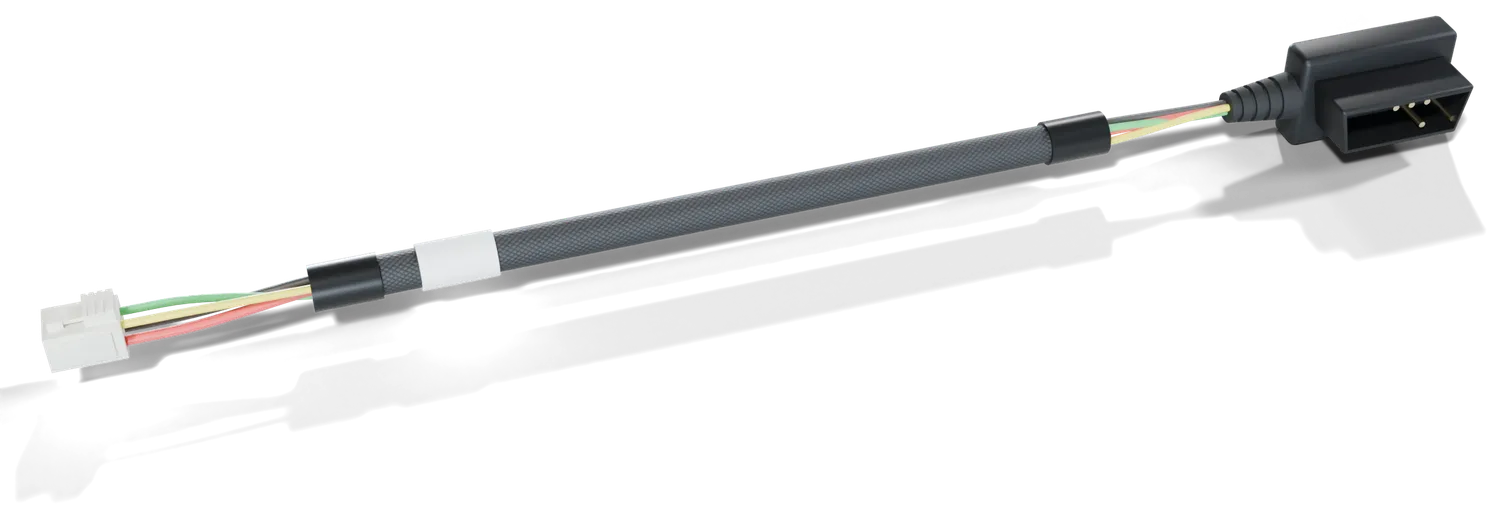
| Pin | Function | Colour | Gauge | Vehicle OBD-II socket pin | Notes |
|---|---|---|---|---|---|
| 1 | Vehicle 12 V | red | 18 AWG (0.8 mm²) | 16 | Battery power from the OBD socket. Protected by a 2 A self-resetting device in the controller. |
| 2 | Ground | black | 18 AWG (0.8 mm²) | 4 (and 5) | Chassis and signal ground are linked inside the plug. |
| 3 | CAN high | yellow | 20 AWG (0.5 mm²) | 6 | Twisted pair with pin 4. |
| 4 | CAN low | green | 20 AWG (0.5 mm²) | 14 | Twisted pair with pin 3. |
Harness A is fully terminated at both ends; there is nothing to wire. If your vehicle's OBD socket is not powered with the key off, the controller will only be awake with the ignition on unless you also fit the dedicated feed. Vehicles whose diagnostic socket does not use CAN on pins 6 and 14 will power the controller but will not provide vehicle data; use the IGN lead for a verified ignition state. Ignition on does not prove that the engine is running.
The vehicle's OBD-II socket
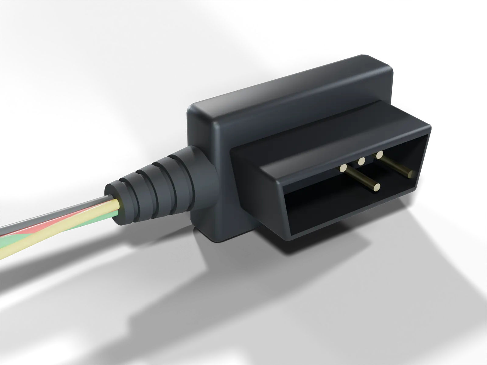
| Socket pin | Vehicle signal | Harness A wire | What FusionDrive does with it |
|---|---|---|---|
| 16 | Battery positive, usually always on | red | Powers the controller (2 A self-resetting protection). Most vehicles fuse this pin at 7.5–15 A together with the cigarette lighter or radio. |
| 4 | Chassis ground | black | Controller ground. Pins 4 and 5 are linked inside the plug, so either one grounds the controller. |
| 5 | Signal ground | ||
| 6 | CAN high | yellow | Supported vehicle data and fault-code services, with wake-on-traffic where configured. Available parameters depend on the vehicle ECU. |
| 14 | CAN low | green |
Harness B — Power & outputs 0.5 m
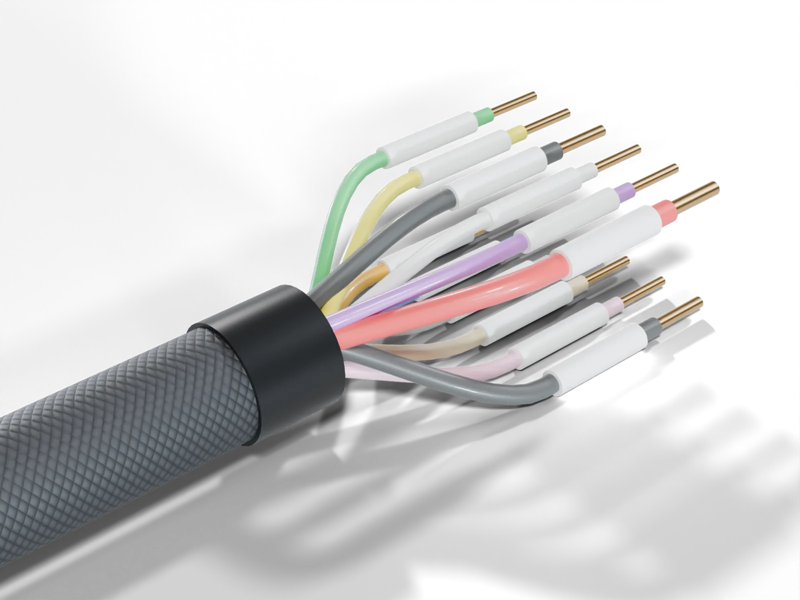
| Pin | Lead label | Function | Colour | Gauge | Rating / range | Notes |
|---|---|---|---|---|---|---|
| 1 | BATT+ 30A | Dedicated battery feed | red | 12 AWG (3.3 mm²) | 12 V feed; 30 A fused path | Dedicated battery positive through a correctly sized battery-end fuse, no larger than the 30 A path limit. Required for OUT1–4. LS Rev A can falsely indicate feed presence when unplugged; verify the actual supply. |
| 2 | AUX1 LS 1A | Low-side auxiliary output 1 | violet | 16 AWG (1.3 mm²) | Ground-switching sink, nominal 1 A-class, PWM | Connect a compatible load between its fused +12 V supply and AUX1. Requires common ground, correct suppression and validated power sequencing. Does not supply 12 V. |
| 3 | IGN | Ignition sense | white | 16 AWG (1.3 mm²) | 12 V in, sense only | Ignition-switched 12 V sense/wake input. Configure and verify ignition-dependent logic. Not a physical OUT1–4 supply interlock; never wire permanent battery positive here. |
| 4 | GND | Ground | black | 14 AWG (2.1 mm²) | Power ground / return | Chassis ground. Connect both GND leads (pins 4 and 7). |
| 5 | CAN2 H | CAN 2 high | yellow | 16 AWG (1.3 mm²) | CAN bus | Separate CAN2 interface for compatible accessories; not internally bridged to CAN1 and not a claim of galvanic isolation. Start listen-only; verify bitrate, termination and signal definitions. Twisted pair with pin 6. |
| 6 | CAN2 L | CAN 2 low | green | 16 AWG (1.3 mm²) | CAN bus | Twisted pair with pin 5. |
| 7 | GND | Ground | black | 14 AWG (2.1 mm²) | Power ground / return | Chassis ground. Second return path; must be connected. |
| 8 | AUX2 LS 1A | Low-side auxiliary output 2 | pink | 16 AWG (1.3 mm²) | Ground-switching sink, nominal 1 A-class, PWM | As AUX1. |
| 9 | OUT4 10A | Output 4 | tan | 16 AWG (1.3 mm²) | High-side 12 V PWM; designed for 10 A | Positive-side output from the dedicated feed. Shares the 30 A fused path; actual load and thermal capability require validation. |
| 10 | OUT3 10A | Output 3 | grey | 16 AWG (1.3 mm²) | High-side 12 V PWM; designed for 10 A | Positive-side output from the dedicated feed. Shares the 30 A fused path; actual load and thermal capability require validation. |
| 11 | OUT2 10A | Output 2 | blue | 16 AWG (1.3 mm²) | High-side 12 V PWM; designed for 10 A | Positive-side output from the dedicated feed. Shares the 30 A fused path; actual load and thermal capability require validation. |
| 12 | OUT1 10A | Output 1 | orange | 16 AWG (1.3 mm²) | High-side 12 V PWM; designed for 10 A | Positive-side output from the dedicated feed. Shares the 30 A fused path; actual load and thermal capability require validation. |
OUT1–4 have built-in high-side PWM power drivers designed for 10 A each, sharing a 30 A fused power path. Compatible loads connect directly; no extra driver is needed within their electrical requirements. Check running and start/stall current, wiring, connectors, fuse protection, cooling and enclosure temperature for the actual installation; reduce the load or use a suitable external driver where needed. Do not plan four 10 A loads at once. AUX1–2 are nominal 1 A-class low-side sinks. The load connects from fused +12 V to AUX, with a common power ground. OUT1–4 instead connect to load positive; load negative returns to ground. Neither output type is an isolated contact.
On the LS Rev A assembly, an unplugged dedicated feed can backfeed the load rail and produce a false feed indication or an unstable heavy-output supply. Fit the dedicated fused feed before using OUT1–4. Verify it at J6 pin 1 with a meter; the app or LED alone is not proof. Software cannot correct this power-path issue.
IGN is a sense/wake input, not a physical load-power interlock. Configure and test key-off output behaviour. Choose compatible inductive suppression using the separate high-side and low-side examples below.
The supplied wire gauges do not establish the current capability of the board, connector or installed assembly. Validate the complete path, including start/stall current and heat. Controllers, EBC triggers and automations share six channels: there are four heavy outputs and two small AUX sinks, not six interchangeable power drivers.
Harness C — Sensor inputs 0.5 m
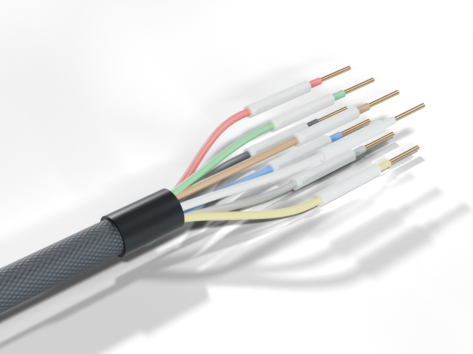
| Pin | Lead label | Function | Colour | Gauge | Range | Notes |
|---|---|---|---|---|---|---|
| 1 | IN1 | Input 1 | white | 20 AWG (0.5 mm²) | 0–5 V | Analog or level/switch. App name: IN1. |
| 2 | IN2 | Input 2 | brown | 20 AWG (0.5 mm²) | 0–5 V | App name: IN2. |
| 3 | IN3 | Input 3 | green | 20 AWG (0.5 mm²) | 0–5 V | App name: IN3. |
| 4 | +5V OUT | Sensor supply | red | 20 AWG (0.5 mm²) | 5 V out; keep combined sensor draw below ≈500 mA | For compatible 5 V sensors; shares the board rail. Allow margin. Not for pumps, lamps, relays or wideband heaters. |
| 5 | IN4 | Input 4 | yellow | 20 AWG (0.5 mm²) | 0–5 V | App name: IN4. |
| 6 | IN5 | Input 5 | grey | 20 AWG (0.5 mm²) | 0–5 V | App name: IN5. |
| 7 | IN6 | Input 6 | blue | 20 AWG (0.5 mm²) | 0–5 V | App name: IN6. |
| 8 | GND | Sensor ground | black | 20 AWG (0.5 mm²) | — | Reference for all sensors. Do not use as a load return. |
Input behaviour
- Voltage compatibility: inputs accept conditioned 0–5 V signals. Never connect 12 V, a coil/ignition signal or a negative-going signal directly. Input clamps are not permission to miswire; an overvoltage or transient can damage the controller or the connected sensor.
- Zero is a reading, not a diagnosis: an open input tends toward 0 V, but 0 V may also be a valid sensor value. A zero reading, freshness flag or app label does not prove a wire is intact. Check the sensor's documented failure voltages and test the chosen fault response.
- Calibration: analog inputs use the voltage/value calibration you set. Presets are starting points; enter the correct units, range and calibration from the actual sensor or conditioner.
- Level/switch mode: the default threshold is 2.5 V. Threshold, hysteresis and reverse logic are configurable. Verify both states and the disconnected-wire state before using a switch as an arm or safety input.
- Sensor supply: J8 pin 4 supplies 5 V for compatible sensors and shares the board's 5 V rail. Keep the combined external sensor draw below the hardware guide's approximately 500 mA allowance, with margin. It is not a pump, lamp, relay or wideband-heater supply.
- Sensor reference: use J8 pin 8 sensor GND as the signal reference. Do not use it as a load return. Before sharing an existing sensor signal, verify its output type, voltage, grounding and permitted additional loading with the device maker.
- Pulse and specialised sensors: these multiplexed analog inputs are not dedicated frequency counters. Frequency-output flex-fuel or flow sensors, crank/cam signals and raw thermocouples need a compatible conditioner or a supported, defined CAN signal. Selecting a preset does not add the missing interface.
- Freshness: input conversion, CAN/OBD acquisition and phone display rates differ. Use the actual source age and configured stale limits; a faster display or recording setting does not make the sensor update faster.
Typical wiring diagrams
These LS wiring examples show connection polarity; they do not qualify every pump, valve, controller or relay. Fuse values are illustrative or shared-path limits, not continuous-current ratings. Verify the actual load, start/stall current, wiring, driver, suppression and heat before connecting it. OUT1–4 require the dedicated feed; all connected supplies need the correct common reference.
Dedicated power feed and ignition sense
Three-wire 0–5 V pressure sensor
Two-wire temperature sender
Level switch, float switch or arm switch
High-current pump on an output
Relay on an auxiliary output
Boost control solenoid
Low-side alternative: a compatible small solenoid may instead connect from fused +12 V to AUX1 or AUX2, with its negative terminal on AUX. Use the LS diode orientation shown in the relay example: stripe/cathode to +12 V, anode to AUX. Stay within the nominal 1 A-class interface and validate the actual load and power sequencing.
Water/methanol pump with a tank level switch
Nitrous solenoid with an arm switch
Keeping an external boost controller
FusionDrive can use AUX1 (J6 pin 2), and AUX2 (J6 pin 8) where required, to operate documented ground-trigger selection inputs on a compatible external EBC. The EBC retains its own sensor, control algorithm and solenoid wiring. Choose the matching pulse/group behaviour only after checking the exact controller manual.
Check trigger voltage, sink current, polarity, pull-ups, pulse width, group count and power-on behaviour. Analog, resistor-ladder, isolated-contact or proprietary interfaces need a suitable interface; a brand/preset listing is not universal electrical compatibility. If group restoration is enabled, FusionDrive assumes the external EBC starts at Group 1. Verify that reset synchronisation on the actual device before relying on restored selections. These two AUX channels cannot simultaneously serve other output assignments.
Extending the leads
| Lead | Harness gauge | Minimum extension gauge | Notes |
|---|---|---|---|
| BATT+ 30A | 12 AWG (3.3 mm²) | 12 AWG (3.3 mm²) | Heavier for runs over 2 m. Fuse at the battery. |
| GND (Harness B) | 14 AWG (2.1 mm²) | 14 AWG (2.1 mm²) | Keep short; ground close to the controller. |
| OUT1–OUT4 | 16 AWG (1.3 mm²) | 16 AWG (1.3 mm²) | Select for actual load current, voltage drop, temperature and installation length. |
| AUX1, AUX2, IGN | 16 AWG (1.3 mm²) | 16 AWG (1.3 mm²) | Match or exceed the supplied gauge; AUX load current returns through its lead. |
| CAN2 H / L | 16 AWG (1.3 mm²) | 18–20 AWG twisted pair | Keep the pair twisted to within 25 mm of each end. |
| IN1–IN6, +5V OUT, GND (Harness C) | 20 AWG (0.5 mm²) | 20 AWG (0.5 mm²) | Twisted or shielded for long or noisy runs; shield to Harness C GND at the controller end only. |
- Use crimped butt splices or heat-shrink splice sleeves, then adhesive-lined heat shrink over the joint.
- Use automotive thin-wall wire rated to at least 105 °C; 125 °C in the engine bay.
- Keep sensor wiring away from output wiring and ignition components.
Optional ignition sense with OBD
J6 pin 3 remains the dedicated IGN sense input. It is optional for software vehicle-activity detection when fresh running-engine OBD data is available; either or both sources may be used. IGN is not a load-power feed. Preserve all documented output, ground and CAN pin assignments.