
Technical specifications
Ratings, ranges and limits for the FusionDrive controller, its harnesses and the app. Where a figure is still being finalised for production it is marked as such rather than guessed.
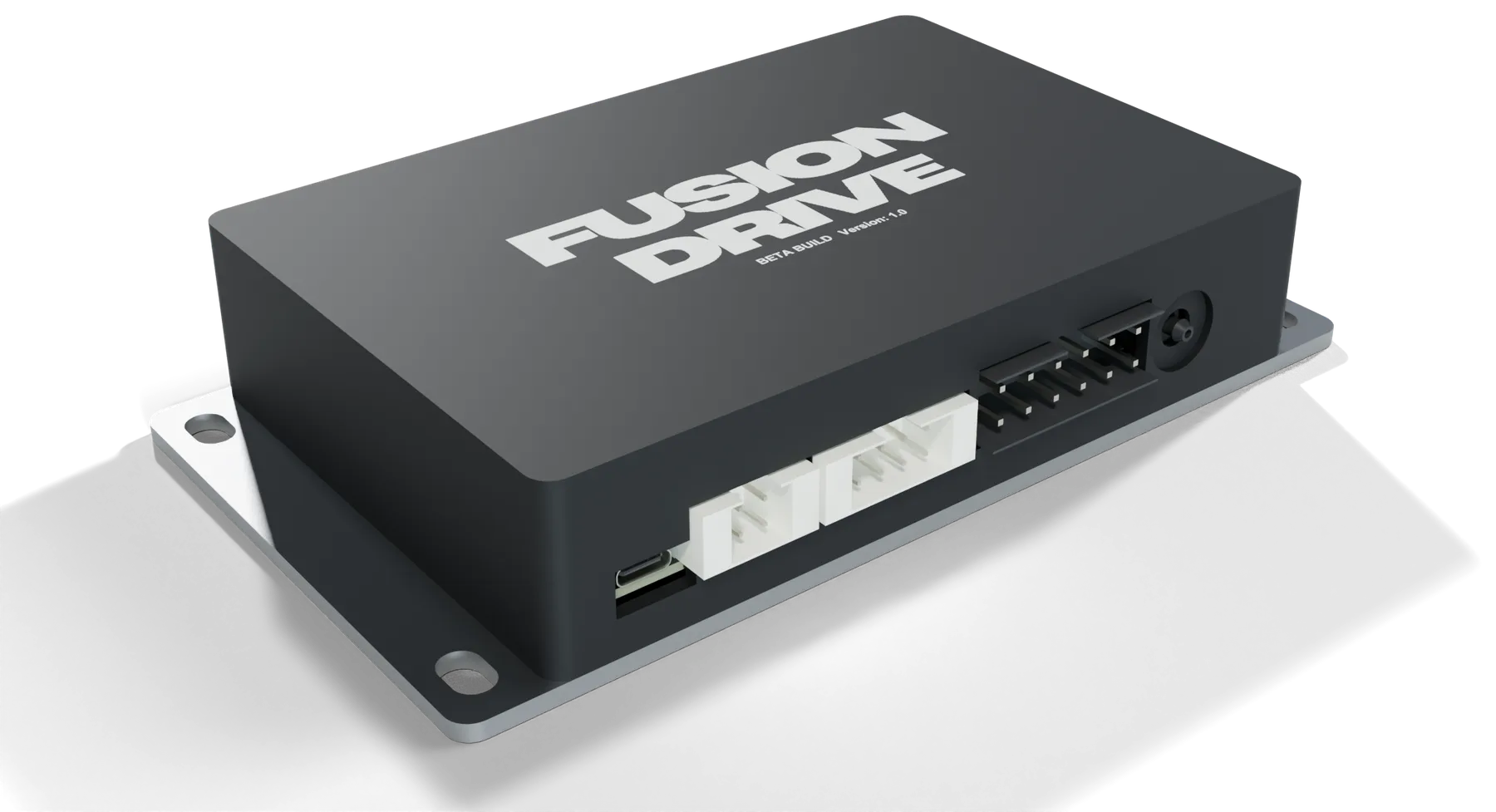
At a glance
6 sensor inputs
0–5 V analog or level/switch, with a 5 V sensor supply.
6 PWM outputs
4 high-side OUT + 2 low-side AUX (nominal 1 A-class). All PWM-capable.
Vacuum to 60 psi
Built-in gauge boost/vacuum sensor with a 2 mm hose barb.
OBD-II + CAN 2
Vehicle bus over the OBD-II socket plus a private second CAN bus.
Bluetooth + Wi-Fi
Bluetooth to the iPhone app and CarPlay; Wi-Fi for firmware updates.
12 V, 30 A
OBD-powered (2 A) or a dedicated 30 A fused feed.
Electrical & power
| Supply voltage | 12 V nominal vehicle system. Use within the validated assembly and accessory supply limits. Not for 24 V vehicles; automotive transient and environmental qualification remains part of beta hardware testing. |
|---|---|
| Power sources | Harness A provides vehicle supply for logic, sensing and communication. OUT1–4 require the dedicated fused feed on J6 pin 1. AUX1/2 are ground-switching outputs: they do not source power to a load. On Rev A-LS, the dedicated-feed indication can be affected by a documented backfeed path; verify the actual feed electrically. |
| OBD feed protection | 2 A self-resetting protection inside the controllerRecovers by itself once the overload is removed. |
| Dedicated feed protection | 30 A mini blade fuse inside the controllerPlus the 30 A fuse the installer fits at the battery, which protects the harness. |
| Shared output supply | OUT1–4 are designed for 10 A each and share a 30 A fused supply path. Compatible loads use the built-in drivers directly. Design ratings still require validation of continuous current for the complete board, connectors, enclosure or simultaneous PWM loads. Validate the installation and each load. |
| Ignition sense input | IGN lead, 12 V ignition-switched, sense only (about 0.2 mA)High = key on. Used by configured wake and control logic. It is not a physical power interlock for OUT1–4. Wire and test it according to the installation guide. |
| Sleep behaviour | Configured activity, ignition and sleep policy determine entry and wake. Test wake timing and current on the delivered board; the software’s timers are not a measured vehicle response guarantee. |
| Sleep current | About 1–2 mA at 12 V (design figure)Roughly 0.03–0.05 Ah per day: two weeks parked costs under 1 Ah. Final production figure to be confirmed after validation. |
| Power-up state | Saved configuration is restored. Manual duty resets to zero, prime is transient and nitrous starts disarmed. Review saved local rules and controller startup behavior before connecting loads. |
| Grounding | Two 14 AWG ground leads on Harness B (both must be connected); separate sensor ground on Harness C |
Sensor inputs
| Number of inputs | 6 (IN1–IN6), on Harness C |
|---|---|
| Input range | 0–5 V conditioned analog input. Keep the signal within this range and use the correct common reference. Do not apply 12 V, negative voltage or an unconditioned ignition/crank signal. |
| Sensor types | Documented 0–5 V outputs, appropriately conditioned resistive/temperature sensors and correctly biased slow switches. Pulse/frequency flow or flex-fuel sensors need a suitable converter or CAN accessory. Sharing an existing sensor requires checking loading, grounding and the original equipment’s requirements. |
| Level / switch threshold | Configure digital mode, inversion, thresholds and debounce for the actual switch circuit. Verify both open and closed values; do not assume an open circuit means zero. |
| Unconnected input | An unconnected or zero-volt input is not a universal absence detector. Set expected range, validity and stale behavior and verify the signal before using it as a protection or automation condition. |
| Resolution | Better than 1 mV at the input (about 0.2 mV) |
| Input load | The input conditioning loads and filters the source. Confirm the sensor/controller can drive it without changing the reading seen by existing equipment; compatibility is not established by the voltage range alone. |
| Protection | Conditioning and clamps do not authorize overvoltage or reversed wiring. A wiring mistake may damage the sensor, FD or connected equipment. |
| Update rate | Six channels share multiplexed ADC conversion. Filtering, channel count and firmware service cadence affect freshness. A requested 50 Hz log can contain repeated source values; inspect source ages and acquisition gaps. |
| Sensor supply | J8 pin 4 provides a 5 V sensor supply, with sensor ground on pin 8. Confirm the combined sensor current and wiring against the delivered hardware specification. Do not join it to another device’s 5 V regulator. |
| Built-in presets | External Boost / MAP, Oil Pressure, Fuel Pressure, Ethanol Content, EGT, 0–5 V Generic, Level / SwitchAny input can also be scaled manually with two voltage/value points. |
Outputs
| Number of outputs | 6 — OUT 1, OUT 2, OUT 3, OUT 4, AUX 1, AUX 2 — on Harness B |
|---|---|
| Type | OUT1–4 are high-side 12 V outputs: OUT → load positive, load negative → common ground. AUX1/2 are low-side sinks: fused compatible supply → load positive, load negative → AUX. AUX is neither an analog voltage output nor an isolated relay contact. |
| OUT 1–4 load capability | Four outputs on a shared 30 A fused path, requiring a correctly fused dedicated feed. Individual/simultaneous continuous load, inrush, PWM and thermal capability must be validated on the assembly; component or lead labels are not that validation. |
| AUX 1–2 load capability | Nominal 1 A-class low-side circuits on J6 pins 2 and 8. Use documented compatible ground-trigger inputs or suitably rated loads. Common ground, load supply and power sequencing must suit the circuit. |
| PWM frequency | 1 Hz – 40 kHz, set per outputPresets: Boost Solenoid 30 Hz · Nitrous Solenoid 100 Hz · Fuel Pump 250 Hz · WMI Pump 500 Hz · Generic 1 kHz · Cooling Fan 25 kHz (inaudible) |
| Duty range | 0–100 % in 1 % steps, with per-output minimum and maximum limits and ramp ratesFuel Pump preset enforces a 30 % minimum duty. |
| Load types | Compatible pumps, fans, solenoids, relay coils or external control inputs within the selected channel’s capability. Match inductive suppression to the load: diode cathode/stripe goes toward load positive. That is OUT for a high-side circuit, but the fused positive supply for low-side AUX. |
| Protection | Fuse the supply and each load to protect its wiring and validated current limit. The board does not measure per-output current, voltage, pump rotation or fluid flow. A commanded duty or logical fault state is not proof of electrical load health. |
| Arbitration | Controller assignments share six physical channels. Conflicting assignments are rejected. Output commands, automation actions and configured protective cuts follow firmware arbitration; installation-specific physical protection remains necessary. |
Built-in boost sensor
| Type | Gauge pressure, referenced to the air around the controllerReads boost and vacuum directly; no barometric correction needed. |
|---|---|
| Range | Full vacuum to +60 psi (414 kPa) boostSensor span is −60 to +60 psi; readings below atmospheric show as negative (vacuum). |
| Resolution | About 0.03 psi (0.2 kPa) |
| Accuracy | Use the exact fitted sensor’s specification and calibrate the assembled installation. Bench/vehicle measurement is required before relying on it for a protective threshold. |
| Update rate | Read continuously; used by the boost controller 50 times a second |
| Port | Barbed hose fitting on the connector face, about 2 mm acrossSuits 2 mm (5/64 in) bore silicone vacuum hose; use a T-piece with a 2 mm leg or a 4 → 2 mm reducer to join the vehicle's 3–4 mm line. Air only: the sensor tolerates humidity and fuel vapour but never connect liquids. |
| Fallback | AUTO retains the supported onboard/OBD policy. Explicit feedback selection uses the chosen calibrated input and does not silently substitute another source. An unplugged pressure hose may still produce plausible pressure and cannot be assumed detectable. |
CAN & OBD-II
| CAN 1 — vehicle bus | Via the OBD-II socket (pins 6 and 14) on Harness A |
|---|---|
| Protocol | Supported OBD-II over classical CAN, with configurable bus speed and standard/extended identifiers. Match the vehicle or accessory definition. The MCP2518FD hardware does not mean the current firmware implements full CAN FD data-phase operation. |
| Vehicles | Compatible 12 V vehicles with supported CAN-based OBD diagnostics. An OBD-II socket alone does not guarantee coverage; non-CAN diagnostic protocols are not provided through these CAN channels. |
| Live data | Discovery lists supported responses exposed by the vehicle and understood by FD. Availability and rate depend on the ECU, session and decoder. Proprietary signals need correct custom definitions; listening to bytes does not reveal their meaning automatically. |
| Fault codes | Read stored, pending and permanent fault codes with descriptions; clear codes |
| Operating modes | Auto (listen first, then request), Active (request), Passive (listen only, for aftermarket ECUs that broadcast, such as Haltech) |
| Decoding | Up to 70 configured decode rules, saved on FD so decoding and eligible local control continue without the phone. Full drive recording still requires the iPhone. DBC import supports the app’s implemented subset; review imported definitions and units. |
| Transmit | Up to 8 custom frames broadcasting FusionDrive sensor values onto the bus (raw, or OBD-style responses) at 1–100 Hz |
| CAN 2 — private bus | A separate accessory bus on Harness B CAN2 H/L. Configure bus speed, listen-only/transmit permission and supported signal definitions for the accessory. General accessory-specific polling is not implemented; only supported configured transmissions may be sent. Saved decoded signals can feed eligible controllers, rules and selected log channels. Future FD add-ons require their own compatible definitions. |
Connectivity
| Phone connection | Bluetooth LE to the iPhone app. Actual update rate and reliability depend on channel selection, source rates, negotiated transport and radio conditions; no fixed rate is guaranteed for every signal. |
|---|---|
| Identification | Each controller advertises under its serial number, printed on the unit |
| CarPlay | Dashboard, boost, outputs, OBD and automations on the vehicle's screen through the paired iPhone |
| Wi-Fi | 2.4 GHz Wi-Fi, used only for firmware updates from the FusionDrive update serverEnter network details in the app; the controller connects, downloads, verifies and reboots. Not required for normal operation. |
| Cloud | Optional FusionDrive account for drive logs, remote configuration and Intelligence briefs, via the app |
| Service port | Wired service connection for workshops and support; not used in normal operation |
| Security | Per-device claim code links a controller to an account. A PIN protects the separate connected configuration-snapshot tool, not general control access. |
Control features
| Boost control | Manual duty, open-loop tables or closed-loop PID; profiles, RPM targets, gear-by-RPM grids, speed/elapsed-load-time curves, source bindings and configured gates/protections. |
|---|---|
| Water/methanol | Progressive pump control, external monitoring or compatible binary interlock. Duty tables, priming, flow/pressure/level bindings and thresholds, grace/debounce/recovery and optional linked boost cut. Installed measurements are required for measured-delivery protection. |
| Nitrous | Up to three wet/dry stages and three profiles, with independent nitrous/fuel progression, time/RPM curves, gates, delays and limits. Selected fuel/bottle pressure and measured AFR/lambda protection require valid signals. Optional binary retard request needs a compatible external interface. |
| Automations | Up to 10 local rules, 8 conditions and 8 actions per rule, nested logic, hysteresis, delays, timed holds and bounded links between rules. Cycles are rejected and controller output ownership is respected. |
| External boost controller | One or two AUX channels can pulse documented compatible ground-trigger inputs. Model names are pulse presets, not proof of electrical compatibility. FD’s assumed group is not a readback of the external controller’s actual group. |
| Configuration storage | Operating settings, sensor calibration, bus/decoder definitions, controllers and automations are saved on FD after acknowledgement. Phone and web hold views/drafts; Cloud changes require review through the connected app and FD readback. Drive logs live on the phone and optional Cloud. |
Environmental
| Mounting environment | Cabin, or a dry, ventilated engine-bay location away from exhaust heat |
|---|---|
| Operating temperature | Final assembly temperature and load limits follow physical validation. Keep the beta unit away from exhaust heat, liquids and unsupported load conditions; a component temperature rating is not a complete enclosure rating. |
| Ingress | Splash-resistant only; not rated for submersion or direct spray (no IP rating claimed for the beta build)Mount with the connector face down or sideways where water could reach it. Plugs are latching but not sealed. |
| Cooling | Passive. The steel base plate conducts heat from the outputs into whatever it is bolted to; no fan, no vents. |
| Vibration | Solid mounting with four M6 bolts; harnesses supported within 150 mm of the controller |
Mechanical
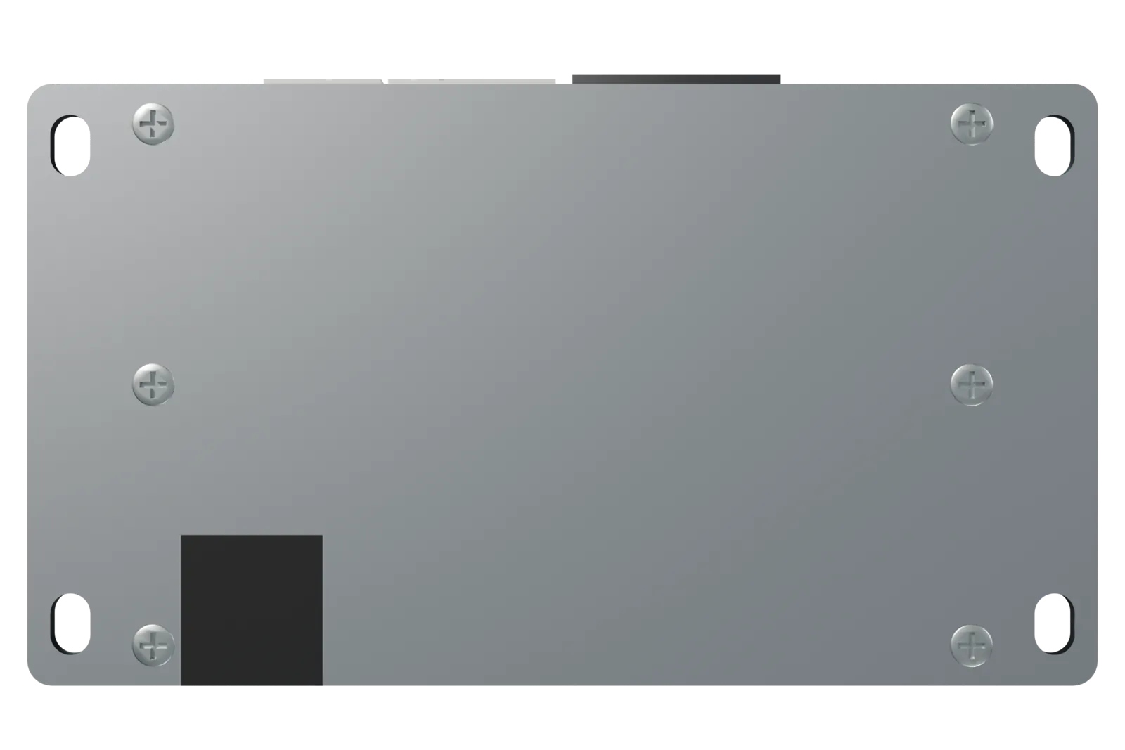
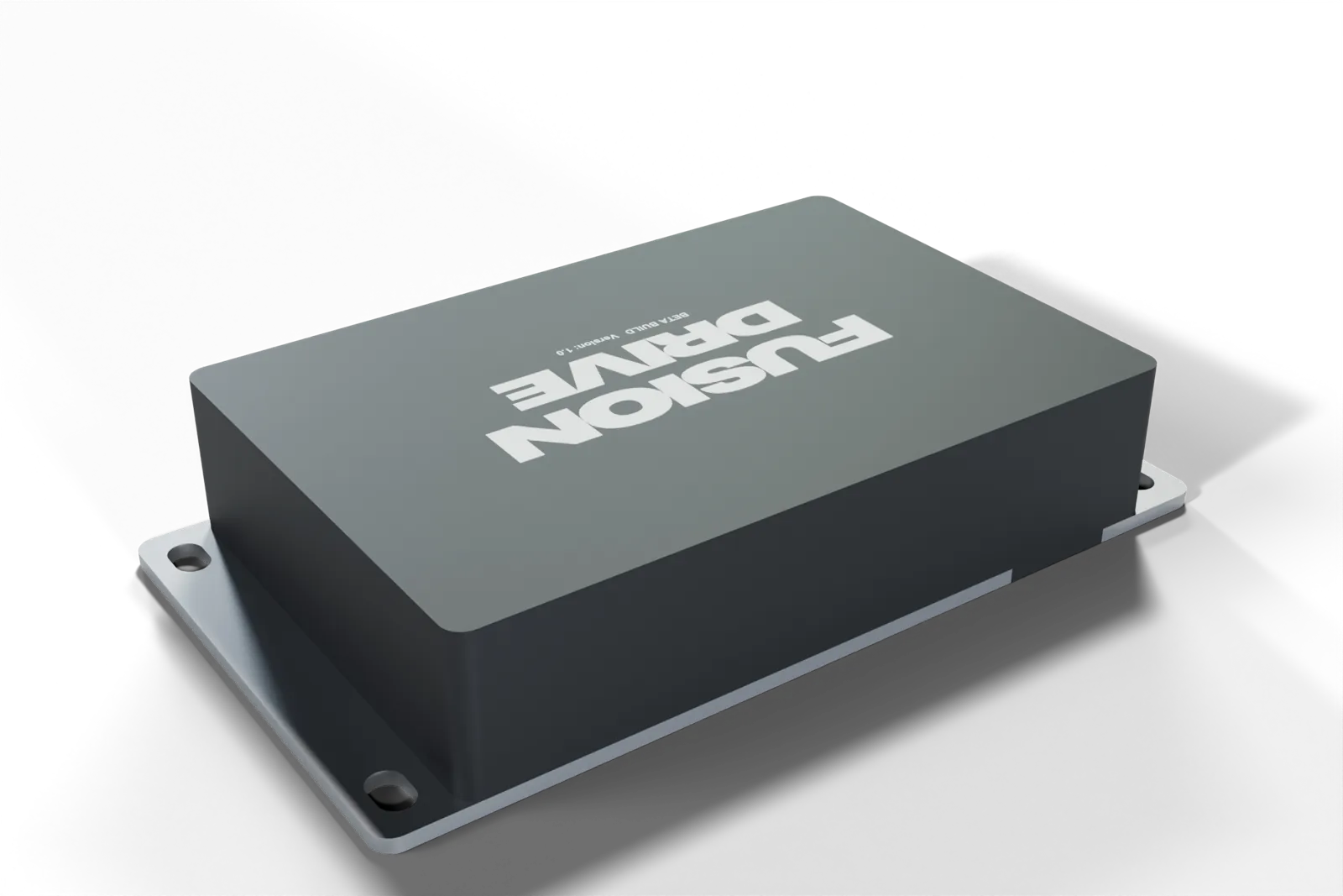
| Body dimensions | 146 × 98 × 34 mm (L × W × H) excluding plugs and barb |
|---|---|
| Overall width including mounting flanges | 174 mm |
| Mounting | 4 slots, 6.5 mm × 10 mm, on 160 mm × 78 mm centres, for M6 (or ¼ in) boltsSlot long axis runs front to back, giving ±2.5 mm adjustment. |
| Clearance | Allow 60 mm in front of the connector face for plugs and cable bend |
| Enclosure | Black high-temperature polymer cover, 2.5 mm walls; 3 mm steel base plate with raised heat-transfer pads under the output stage |
| Weight | Approximately 550 g, controller only (estimate for the beta build from the plate and cover dimensions; final figure to be confirmed) |
| Connections | 4-way OBD port · 8-way sensor port · 12-way power & outputs port · boost barb · service port. All plugs latching and keyed. |
Harnesses
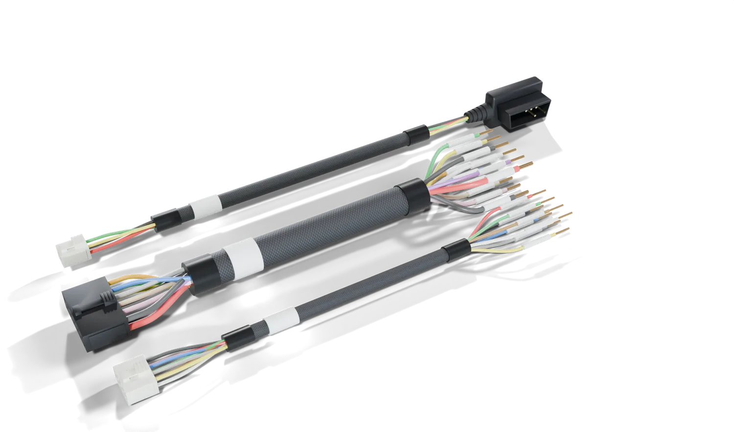
| Harness | Port | Length | Far end | Wire |
|---|---|---|---|---|
| A — OBD-II | OBD port, 4-way | 1500 mm (+10 / −0) | Low-profile side-exit OBD-II plug, ≤18 mm proud of the socket | 18 AWG power/ground, 20 AWG twisted CAN pair |
| B — Power & outputs | Power & outputs port, 12-way | 500 mm (+10 / −0) | 12 labelled flying leads, stripped and tinned; 400 mm sleeved, 100 mm free | 12 AWG feed, 14 AWG grounds, 16 AWG outputs/signals |
| C — Sensor inputs | Sensor port, 8-way | 500 mm (+10 / −0) | 8 labelled flying leads, stripped and tinned | 20 AWG throughout |
Lengths are measured from the plug face to the far end. All wire is thin-wall automotive grade rated to 125 °C, sleeved in braided loom with printed heat-shrink labels rated for engine fluids and temperatures. Full pinouts are in the wiring reference. A 2.0 m OBD harness is available on request.
App requirements
| Platform | iPhone running iOS 18 or later |
|---|---|
| CarPlay | A compatible wired/wireless CarPlay head unit and supported app distribution, via the paired iPhone |
| Connection | Bluetooth (always) · Internet for cloud sync, Intelligence and update checks (optional) |
| Account | Free FusionDrive account for cloud features; the controller works fully without one |
| Firmware updates | Delivered over Wi-Fi from the FusionDrive update server; the app notifies you when one is available |
Warranty & regulatory
Warranty terms, regulatory approvals (radio, EMC) and conformity markings for production units will be published here before general release. Early-build units are supplied for evaluation and are supported directly by FusionDrive.
- Intended use: aftermarket performance and monitoring on 12 V vehicles. The installer is responsible for compliance with local vehicle regulations, including emissions and road-use rules for boost, water/methanol and nitrous systems.
- Not covered: damage from reversed polarity, connection to 24 V systems, unfused loads, liquid in the boost port, or physical modification of the controller or harnesses.
- Support: use Report an Issue in the app (More → Settings → Device & firmware → Report an Issue) to send diagnostics with your request. See troubleshooting.
Source availability
Software vehicle activity accepts dedicated IGN or fresh running-engine OBD evidence. Physical output ratings and wiring do not change with the selected activity source. Selecting OBD pressure is required when the onboard hose is intentionally unused; a valid atmospheric reading does not detect that installation choice.